Inflow hydrograph option
Introduction
This page describes the LISFLOOD inflow hydrograph routine, and how it is used. Inflow hydrographs are optional, and can be activated by adding the following line to the ‘lfoptions’ element in the LISFLOOD settings file:
<setoption name="inflow" choice="1" />
Description of the inflow hydrograph routine
When using the inflow hydrograph option, time series of discharge $[\frac{m^3}{s}]$ are added at some user-defined location(s) on the channel network. The inflow is added as side-flow in the channel routing equations (this works for both kinematic and split routing). Negative inflows (i.e. outflows) are also possible, but have never been verified.
In order to activate the inflow points, LISFLOOD needs a map that defines where we want to add the inflow, and a time series with the corresponding inflow rates.
Inflow map can be a netCDF map or a PCRaster map. It must contain inflow points IDs as integer numbers. Any ID can be used, ID numbers can be consecutive or not.
Time series file are ascii formatted time series that contain inflow values formatted in rows and columns (tss file format). The inflow values in a row are assigned to the cells in the inflow map according to the unique ID that is used in both the tss file and the inflow map. Tss files produced as output by LISFLOOD can be used as inflow tss.
If an inflow ID from inflow map is not available in the tss file, the inflow point is automatically removed and a warning message is printed. Tss files can contain more columns than the number of inflow points in the inflow map.
Tss files with no header can also be used. In this case, tss columns are number progressively and IDs from 1 to the number of columns in the tss file must be used in the inflow map.
Table: Input requirements inflow hydrograph routine.
| Maps | Default name | Description | Units | Remarks |
|---|---|---|---|---|
| InflowPoints | - | locations for inflow hydrographs | - | nominal |
| Time series | ||||
| QInTS | - | inflow hydrograph(s) | $\frac{m^3}{s}$ |
Using the inflow hydrograph option involves four steps:
1) Create a (nominal) map with unique identifiers that point to the location(s) where you want to insert the inflow hydrograph(s)
2) Save the inflow hydrograph(s) in time series format; inflow hydrographs need to be given in $[\frac{m^3}{s}]$
IMPORTANT: when using PCRaster format, you must remember that PCRASTER assumes that the first data series in the time series file (i.e. the second column, since the first column contains the time step number) corresponds to unique identifier 1 on the InflowPoints map; the second series to unique identifier 2, and so on. So, even if your InflowPoints map only contains (as an example) identifiers 3 and 4, you still need to include the columns for identifiers 1 and 2!! The best thing to do in such a case is to fill any unused columns with zeroes (0). Also, your inflow hydrograph time series should always start at t=1, even if you set StepStart to some higher value. For more info on time series files please have a look at the PCRaster documentation.
3) Make sure that the names of the map and time series are defined in the settings file
In the ‘lfuser’ element (replace the file paths/names by the ones you want to use):
	<group>
	<comment>
	**************************************************************
	INFLOW HYDROGRAPH (OPTIONAL)
	**************************************************************
	</comment>
	<textvar name="InflowPoints"
	value="/floods2/yourhomedir/yourcatchment/maps/inlets.map">
	<comment>
	OPTIONAL: nominal map with locations of (measured)
	inflow hydrographs [cu m / s]
	</comment>
	</textvar>
	<textvar name="QInTS"
	value="/floods2/yourhomedir/yourcatchment/inflow/inflow.tss">
	<comment>
	OPTIONAL: observed or simulated input hydrographs as
	time series [cu m / s]
	Note that identifiers in time series correspond to
	InflowPoints map (also optional)
	</comment>
	</textvar>
	</group>
4) Activate the inflow hydrograph option by adding the following line to the ‘lfoptions’ element:
<setoption name="inflow" choice="1" />
Now you are ready to run the model with the inflow hydrograph.
Substituting subcatchments with measured inflow hydrographs
One of the most common uses of the inflow hydrograph option is this: suppose we have a catchment where we only want to simulate the downstream part. If measured time series of discharge are available for the upstream catchment(s), we can use these to represent the inflow into the more downstream part. The Figure below shows an example, where we have measured discharge of subcatchment A (just before it enters the main river).
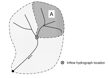
Figure: Using the inflow hydrograph using measured discharge of subcatchment A. MaskMap must have boolean(0) (or missing value) for subcatchment A, see text below for explanation.
In this case it is important to pay special attention to two issues:
1) Exclude subcatchments from MaskMap
First, make sure that subcatchment A is excluded (i.e. have boolean(0) or missing value) on LISFLOOD’s MaskMap (which defines which pixels are included in the calculations and which are not). If you include it, LISFLOOD will first simulate discharge coming out of subcatchment A, and then add the (measured) inflow on top of it! Of course this doesn’t make any sense, so always be careful which areas are included in your simulation and which are not.
2) Make sure your inflow points are where you need them
If you already have all gauge locations on a map, these mostly cannot be used directly as inflow hydrograph locations. The reason is simple: suppose –in our previous example– we know the outflow point of subcatchment A. This point is the most downstream point within that subcatchment. However, the flow out of subcatchment A is actually added to the main river one cell downstream! Also, if we exclude subcatchment A from our simulation (as explained in the foregoing), this means we also exclude the outflow point of that subcatchment. Because of this, inflow points into the main river are usually located one pixel downstream of the outflow points of the corresponding subcatchment. If you already have a (nominal) map of of your subcatchments, we have an utility that automatically calculates the corresponding out- and inflow points.