Reservoirs
Introduction
This page describes the LISFLOOD reservoirs routine, and how it is used. The simulation of reservoirs is optional, and it can be activated by adding the following line to the ‘lfoptions’ element:
<setoption name="simulateReservoirs" choice="1" />
Reservoirs can be simulated on channel pixels where kinematic wave routing is used. The routine does not work for channel stretches where the dynamic wave is used!
Description of the reservoir routine
Reservoirs are simulated as points in the channel network. The inflow into each reservoir ($I_{res} [\frac{m^3}{s}]$) equals the channel flow upstream of the reservoir. Operational rules for reservoirs are not included implicitly in LISFLOOD, but the model mimics these operational rules by using a number of rules which define reservoir output as a function of the relative filling. The relative filling of a reservoir, $F$, is the ratio between the water volume stored in the reservoir at the computational time $Vt\ [m^3]$ and its total storage capacity $S\ [m^3]$:
\[F = \frac{Vt}{S}\]$F$ varies between 0 and 1.
There are three ‘special’ relative filling levels:
- the ‘conservative storage limit $L_c$, that is the lower limit of reservoir water storage (reservoirs are never completely empty)
- the ‘flood storage limit’ $L_f$, that is the upper limit of the operational relative filling as reservoirs are never filled completly for safety reasons
- the ‘normal storage capacity’ $L_n$, that is the available capacity of a reservoir between $L_f$ and $L_c$.
Three discharge values define the way the outflow of a reservoir is regulated.
- ‘minimum outflow’ ($Q_{min}$, $[\frac{m^3} {s}]$) which is maintained for e.g. ecological reasons;
- ‘non-damaging outflow’ ($Q_{nd}$, $[\frac{m^3} {s}]$) is the maximum possible outflow that will not cause problems downstream; and
- ‘normal outflow’ ($Q_{norm}$, $[\frac{m^3} {s}]$) is the one valid when the reservoir is within its ‘normal storage’ filling level.
$L_c$,$L_f$, $L_n$, $Q_{min}$, $Q_{nd}$, $Q_{norm}$ are input data.
Two calibration parameters, namely $AdjL_n$ and $ResMultQ_{norm}$, are used to modulate the reservoir normal filling $L_n$ (balance between lower and upper limit of reservoir filling) and the normal reservoir outflow $Q_{norm}$. Both the parameters are non-dimensional and they are used as follows:
\[L_{adj,f} = L_n + AdjL_n \cdot (L_f - L_n)\]where $AdjL_n$ can assume values between 0.01 and 0.99.
\[AdjQ_{norm} = ResMultQ_{norm} \cdot Q_{norm}\]where $ResMultQ_{norm}$ can assume values between 0.25 and 2; AdjQ_{norm} must always be larger than $Q_{min}$, and smaller than $Q_{nd}$.
Depending on the relative filling of the reservoir, outflow ($Q_{res},[\frac{m^3}{s}]$) is calculated as:
If $F \le 2 \cdot L_c$, then:
\(Q_{res} = \min(Q_{min}, S \cdot frac{1}{\Delta t_{day}})\) where $\Delta t_{day}$ is 86400 meaning that the total daily inflow I_{res} to the reservoir is released downstream.
If $2L_c \lt F \le L_n$, then:
\[Q_{res} = Q_{min} + (AdjQ_{norm} - Q_{min}) \cdot \frac{F - 2L_c}{L_n - 2L_c}\]If $L_n \lt F \le L_{adj,f}$, then:
\[Q_{res} = AdjQ_{norm}\]If $L_{adj,f} \lt F \le L_f$, then:
\[Q_{res} = AdjQ_{norm} + \frac{F - L_{adj,f}}{L_f - L_{adj,f}} \cdot (Q_{nd} - AdjQ_{norm})\]If $F \gt L_f$, then:
\[Q_{res} = \max ((F - L_f -0.01) \cdot \frac{S}{\Delta t_{day}} , Q_{max})\]
with
$Q_{max} = \min ( Q_{nd} , \max ( 1.2 \cdot I_{res} , AdjQ_{norm} ) )$
and
$\Delta t_{day}$ is 86400 meaning that the amount of water exceeding the flood storage limit is realised to the downstream channel in one day.
Finally, the condition described below is applied in order to prevent outflow values that are too large compared to the inflow value.
If $(Q_{res} \gt 1.2 \cdot I_{res})$ and $(Q_{res} \gt AdjQ_{norm})$ and $(F \lt L_f)$, then:
\[Q_{res} = \max (( F - L_f - 0.01 ) \cdot \frac{S}{\Delta t_{day}} , Q_{reg} )\]where $Q_{reg} = \min ( Q_{nd} , \max ( 1.2 \cdot I_{res} , AdjQ_{norm}) )$
Summary of the symbols:
$S$: Reservoir storage capacity $[m^3]$
$F$: Reservoir fill (fraction, 1 at total storage capacity) [-]
$L_c$: Conservative storage limit [-]
$L_n$: Normal storage limit [-]
$L_f$: Flood storage limit [-]
$Q_{min}$: Minimum outflow $[\frac{m^3} {s}]$
$Q_{norm}$: Normal outflow $[\frac{m^3} {s}]$
$Q_{nd}$: Non-damaging outflow $[\frac{m^3} {s}]$
$I_{res}$: Reservoir inflow $[\frac{m^3} {s}]$
$AdjL_n$: calibration parameter used to modulate $L_n$ [-]
$ResMultQ_{norm}$: calibration parameter used to modulate $Q_{norm}$ [-]
**The reservoir outflow is calculated using the same computational time interval used for the channel routing. **
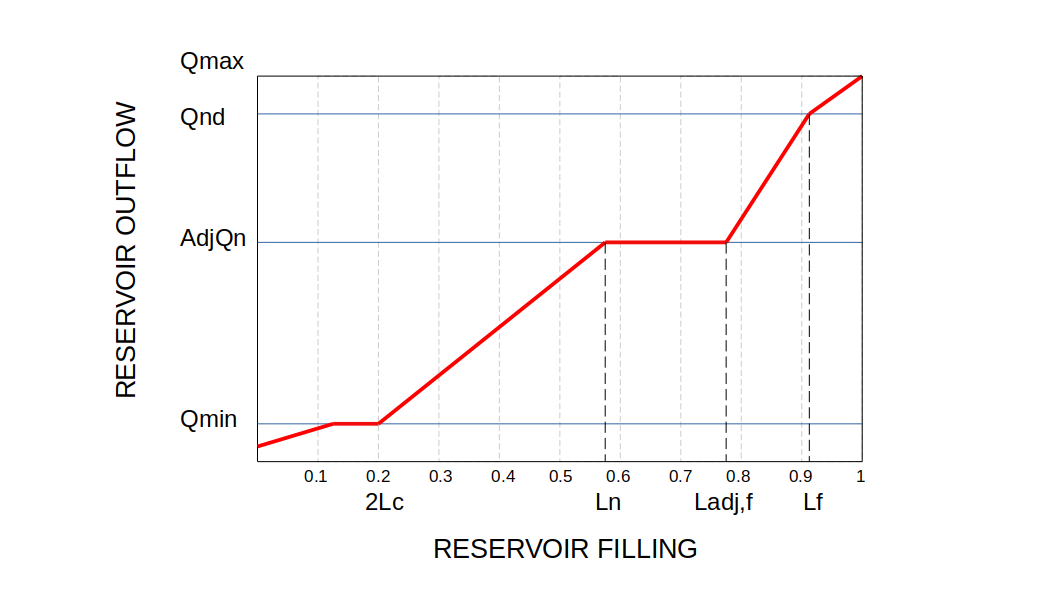
Figure: Schematic of the reservoirs routine.
Preparation of input data
For the simulation of reservoirs a number of additional input files are necessary. First, the locations of the reservoirs are defined on a (nominal) map called ‘res.map’. It is important that all reservoirs are located on a channel pixel (you can verify this by displaying the reservoirs map on top of the channel map). Also, since each reservoir receives its inflow from its upstream neighbouring channel pixel, you may want to check if each reservoir has any upstream channel pixels at all (if not, the reservoir will gradually empty during a model run!). The management of the reservoirs is described by 7 tables. The following table lists all required input:
Table: Input requirements reservoir routine.
| Maps | Default name | Description | Units | Remarks |
|---|---|---|---|---|
| ReservoirSites | res.map | reservoir locations | - | nominal |
| TabTotStorage | rtstor.txt | reservoir storage capacity | $[m^3]$ | |
| TabConservativeStorageLimit | rclim.txt | conservative storage limit | - | fraction of storage |
| TabNormalSt orageLimit | rnlim.txt | normal storage limit | - | capacity |
| TabFloodStorageLimit | rflim.txt | flood storage limit | - | |
| TabMinOutflowQ | rminq.txt | minimum outflow | $[m^3]$ | |
| TabNormalOutflowQ | rnormq.txt | normal outflow | $[m^3]$ | |
| TabNonDamagingOutflowQ | rndq.txt | non-damaging outflow | $[m^3]$ |
When you create the map with the reservoir sites, pay special attention to the following: if a reservoir is on the most downstream cell (i.e. the outflow point, see Figure below), the reservoir routine may produce erroneous output. In particular, the mass balance errors cannot be calculated correctly in that case. The same applies if you simulate only a sub-catchment of a larger map (by selecting the subcatchment in the mask map). This situation can usually be avoided by extending the mask map by one cell in downstream direction.
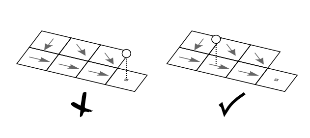
Figure: Placement of the reservoirs: reservoirs on the outflow point (left) result in erroneous behavior of the reservoir routine.
Preparation of settings file
All in- and output files need to be defined in the settings file. If you are using a default LISFLOOD settings template, all file definitions are already defined in the ‘lfbinding’ element. Just make sure that the map with the reservoir locations is in the “maps” directory, and all tables in the ‘tables” directory. Finally, you have to tell LISFLOOD that you want to simulate reservoirs! To do this, add the following statement to the ‘lfoptions’ element:
<setoption name="simulateReservoirs" choice="1" />
Now you are ready to run the model. If you want to compare the model results both with and without the inclusion of reservoirs, you can switch off the simulation of reservoirs either by:
- Removing the ‘simulateReservoirs’ statement from the ‘lfoptions element, or
- changing it into <setoption name=”simulateReservoirs” choice=”0” />
Both have exactly the same effect. You don’t need to change anything in either ‘lfuser’ or ‘lfbinding’; all file definitions here are simply ignored during the execution of the model.
Reservoir output files
The reservoir routine produces 3 additional time series and one map, as listed in the following table:
Table: Output of reservoir routine.
| Maps / Time series | Default name | Description | Units | Remarks |
|---|---|---|---|---|
| ReservoirFillState | rsfilxxx.xxx | reservoir fill at last time step[^10] | - | |
| ReservoirInflowTS | qresin.tss | inflow into reservoirs | $\frac{m^3}{s}$ | |
| ReservoirOutflowTS | qresout.tss | outflow out of reservoirs | $\frac{m^3}{s}$ | |
| ReservoirFillTS | resfill.tss | reservoir fill | - |
Note that you can use the map with the reservoir fill at the last time step to define the initial conditions of a succeeding simulation, e.g.:
<textvar name="ReservoirInitialFillValue" value="/mycatchment/rsfil000.730">